Installation
3D Model Explorer
Interactive 3D model — click and drag to rotate, scroll/pinch to zoom, right-click (or two-finger drag) to pan. Use the toggles below to show or hide each group.
About this guide
This is the field installation manual for the OpenOverland sub-frame on the Ford F-550 chassis (all wheelbases). It covers two sequential operations:
- Mounting the welded steel sub-frame to the truck chassis
- Installing the aluminum cabin floor plate
References: Ford Upfitter Guidelines, AWS D1.1, SAE J429.
Critical safety and pre-install requirements
Read and apply all four before any tooling touches the truck.
Level working surface. The truck must sit on a perfectly flat, solid, level shop floor for the entire install. The chassis must never be twisted, cross-jacked, or unevenly supported. Frame twist during assembly permanently preloads the front pivot mount — accelerated bushing failure and unpredictable off-road behavior follow.
Electrical isolation. Disconnect both vehicle batteries (negative terminal first) before any drilling, positioning, or physical work on the chassis. Voltage spikes during structural work can damage the PCM and body electronics.
Chassis line protection. Existing factory brake lines, high-pressure fuel lines, and electrical harnesses routed inside the frame channels must be physically shielded or temporarily unclipped and moved out of any tooling impact zone.
Ford upfitter constraints. All frame modifications follow official Ford Upfitter Guidelines. Drilling is restricted to the vertical web of the frame channels only. Never drill into the top or bottom horizontal frame flanges — doing so degrades the chassis section modulus and voids the structural warranty.
Tools, machinery, and consumables
Heavy machinery and rigging
- Overhead shop gantry crane, heavy forklift, or engine hoist — minimum 1,100 lb / 500 kg rated lifting capacity
- Heavy-duty load-rated polyester lifting straps/slings and alloy screw-pin shackles
Hand tools and torque equipment
- Wrench set (frame mounts): 2× combination wrenches, or deep sockets with heavy ratchets, sized for the M16 hex — for the M16 structural fasteners ⚠️ confirm across-flats size (was 15/16" for the previous 5/8" hardware)
- Hex key (floor): 1× 4 mm industrial-grade hex key or hex-bit socket — for M6 button-head fasteners
- Calibrated torque wrench, low range: 5–25 Nm (≈ 4–20 ft-lb) — for M6 fasteners
- Calibrated torque wrench, high range: up to 300 Nm (≈ 220 ft-lb) — for M16 chassis bolts
- 4× heavy-duty steel F-clamps or industrial G-clamps, 6" minimum jaw capacity
- Industrial locking grip pliers (Vise-Grips)
- Precision center punch, ball-peen hammer, digital vernier calipers, high-accuracy steel tape (16 ft / 5 m minimum)
Drilling and thread-cutting equipment
- Heavy-duty hand drill or electro-magnetic base core drill (Mag-Drill)
- Cobalt-alloy (HSS-Co) drill bits:
- Ø 5.0 mm — tap drill for M6 threads
- Ø 6.5 mm — clearance drill for M6 fasteners
- Ø 17.0 mm / 0.67" — clearance drill for M16 structural fasteners
- M6 × 1.0 mm machine-grade tap with matching wrench or tap guide
Consumables and shop materials
- Positioning spacer: 1× hardwood or heavy nylon block machined to exactly 40 mm (≈ 1.57") height, minimum 4" × 8" footprint
- Galvanic isolation barrier: weatherproof self-cleaving EPDM rubber foam tape, 3" wide, 1/8" thick, high-tack adhesive (see BOM)
- High-strength threadlocker: Loctite 270 or 2701 (red, permanent)
- Structural adhesive: elastopolymer polyurethane or MS-polymer structural sealant — Sika-Flex 252 or equivalent
- Chemical degreaser / solvent (technical acetone or isopropyl alcohol)
Hardware bill of materials
All structural fasteners and the galvanic isolation tape are McMaster-Carr stock items; PNs link to the product page. Qty needed is the count used in the build; Order is what to buy — rounded up to how McMaster sells each item, since several ship in fixed packs.
| McMaster PN | Item | Spec | Qty needed | Order | Used in |
|---|---|---|---|---|---|
| 91052A123 | Hex head bolt | M16 × 1.5 mm × 60 mm, Class 10.9 | 24 | 24 (sold each) | Ch. I — rear mount (8), pivot mount (8), forward hangers (8) |
| 90965A230 | Washer | 316 stainless, M16 (17 mm ID, 30 mm OD) | 48 | 2 packs of 25 | Ch. I — 2 per bolt (stack top + bottom) |
| 94645A116 | Nylon-insert locknut | M16 × 1.5 mm, zinc-plated, high-strength | 24 | 24 (sold each) | Ch. I — one per bolt |
| 8694K122 | EPDM foam tape | 3" wide × 1/8" thick, self-adhesive | as required | 1 roll, 50 ft | Ch. II — galvanic barrier along sub-frame top run |
| 92095A487 | Button-head screw | M6 × 1.0 mm × 18 mm, 18-8 stainless, hex drive | 12 | 1 pack of 25 | Ch. II — floor (12) |
Buying full 25-packs of the washers (90965A230) and M6 screws (92095A487) already leaves spares; the M16 bolts (91052A123) and locknuts (94645A116) are sold individually, so add 2 extra of each for drops and cross-threads. Floor quantity assumes 6 brackets × 2 holes = 12 — adjust if your floor plate geometry differs.
Chapter I — Sub-frame installation onto the Ford chassis
1Positioning and rear rigging pre-fixation
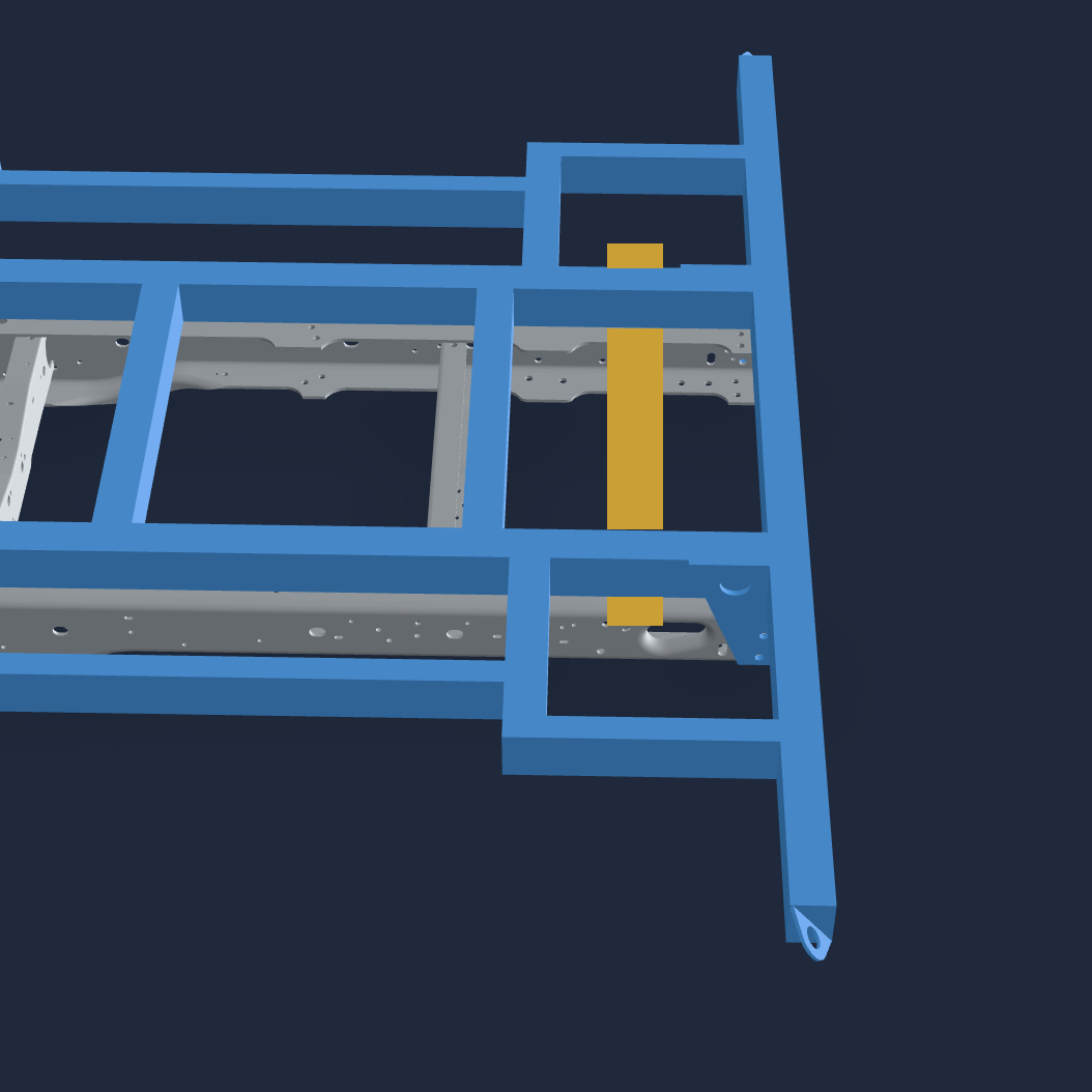
Using a gantry crane or heavy forklift with rated lifting straps, hoist the fully fabricated steel sub-frame above the F-550 chassis rails. Lower slowly until just above contact.
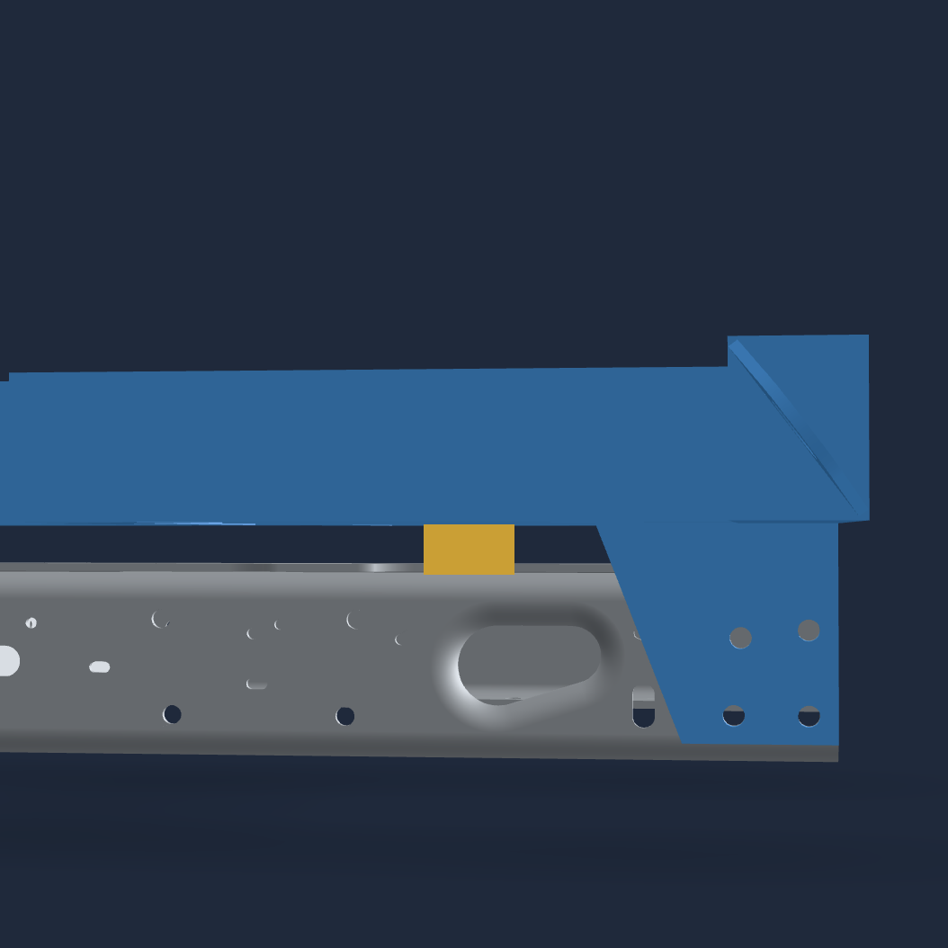
Before final seating, insert the pre-machined 40 mm solid wood block between the top surface of the Ford frame rail and the underside of the sub-frame at the absolute rear edge of the chassis. This temporary block raises the rear of the sub-frame to the exact height needed to align the Ford factory holes with the pre-drilled pattern in the Rear Frame Mount (Component 5).
Once aligned, insert heavy-duty M16 × 1.5 mm hex bolts through all 8 mounting positions of the Rear Frame Mount.
Fastener stack (top to bottom):
Bolt head → stainless washer (90965A230) → sub-frame / chassis bracket matrix → stainless washer (90965A230) → nylon-insert locknut (94645A116).
Bolts: 91052A123 — M16 × 1.5 mm, 60 mm length, Class 10.9.
Thread all 8 nuts hand-tight only at this stage. Do not apply mechanical torque yet — the sub-frame must retain lateral freedom for the next step.
2Lateral alignment and symmetry verification
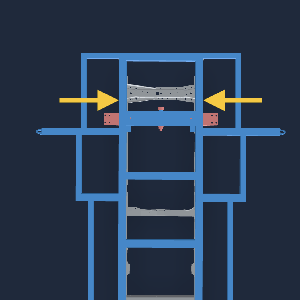
With the rear fasteners hand-tight and the front still floating, the sub-frame can be micro-adjusted laterally on the chassis.
Using digital vernier calipers and precision tape measures, measure from the outer vertical face of the sub-frame main members to the corresponding outer vertical face of the Ford chassis rails. Take readings at a minimum of three synchronized locations:
- Front pivot zone
- Mid-chassis crossmember
- Rear frame mount
Shift the sub-frame until left- and right-hand clearances are identical at every datum.
Tolerance: ± 0.5 mm.
3Final structural torque — rear mounts
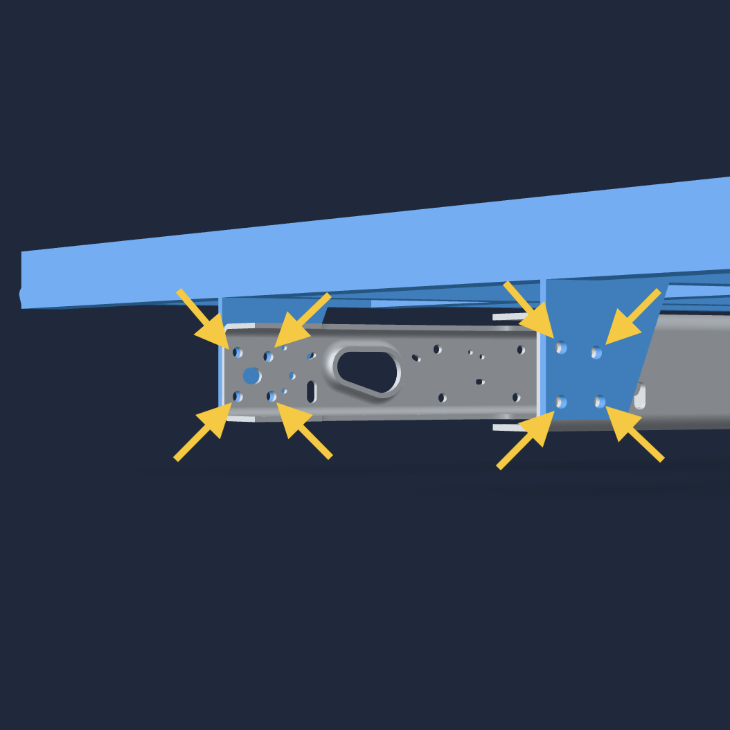
Once tracking symmetry is verified, lock the position with temporary clamps and execute the final torque routine on the 8 rear mounting bolts. Use a calibrated high-range torque wrench in a cross-pattern sequence to distribute clamping stress evenly.
Final torque: all M16 × 1.5 mm Class 10.9 fasteners → 200 Nm (150 ft-lb) ⚠️ verify — value carried over from the previous 5/8" Grade 8 spec.
Immediately after torquing, carefully slide out and remove the 40 mm wood spacer block from the rear frame assembly.
4Positioning of the forward clamping brackets
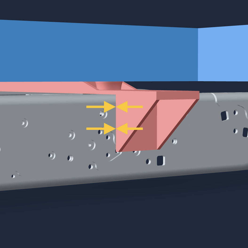
Position both loose heavy-gauge steel components designated Pendulum Mount Attachment to Ford Frame (Component 7 in the main sub-frame BOM / Component 2 in the Pendulum BOM) underneath the lower structural base of the main Subframe Pendulum Mount (Component 3).
Use a minimum of 4 heavy-duty F-clamps to compress the components together.
Critical check:
- Horizontal mating interfaces are perfectly flush — zero gap
- Vertical leg of the Attachment bracket sits completely flat against the vertical web of the Ford chassis rail
5Hole pattern transfer — pivot mount structure
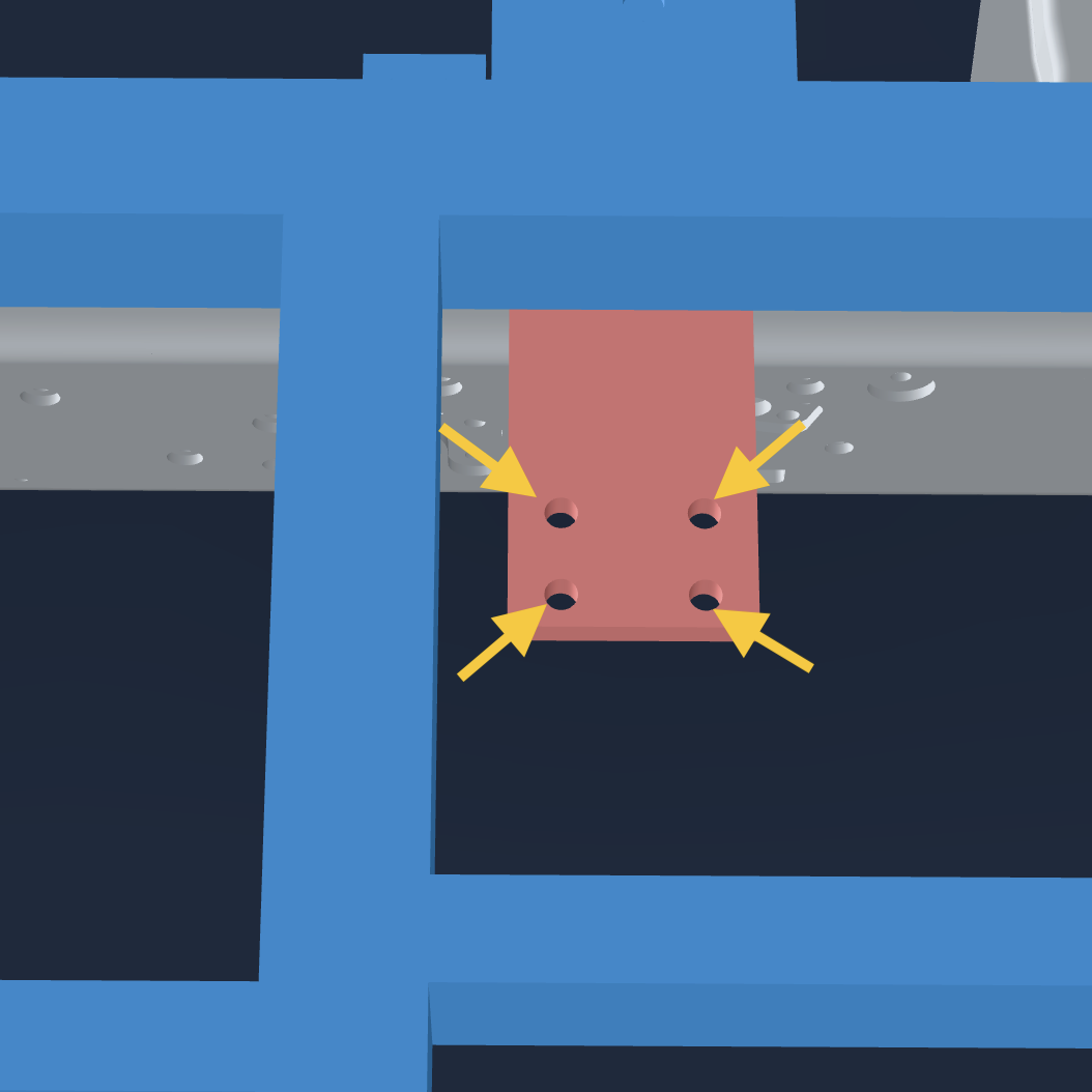
Using the pre-machined holes on the vertical mounting flanges of the Main Crossbeam Pivot Mounting (Component 1) as a physical drilling jig, take a hardened center punch and ball-peen hammer to transfer and punch the hole pattern centers onto the clamped Attachment-to-Ford-Frame brackets.
6Bracket removal and core hole drilling — pivot interface
Loosen the F-clamps and remove the marked brackets from the vehicle. Take them to a stable drill press or set up a mag-drill over the punch marks.
Drill all transferred hole locations to a final structural clearance diameter of Ø 17.0 mm (0.67") using a cobalt bit.
Quality standard: every hole perpendicular to the steel surface. Debur both sides with a 90° countersink to eliminate stress-risers and ensure flush bolt seating.
7Intermediate mechanical fitment to the main crossbeam
Re-install the freshly drilled Attachment-to-Ford-Frame brackets onto the chassis. Secure them to the Main Crossbeam Pivot Mounting flanges using the same fastener combination from Step 1.
Fastener stack (top to bottom):
Bolt head → stainless washer (90965A230) → bracket / Pivot Mounting flange matrix → stainless washer (90965A230) → nylon-insert locknut (94645A116).
Note the two stainless washers — one under the bolt head, one under the locknut.
Bolts: 91052A123 — M16 × 1.5 mm, 60 mm length, Class 10.9.
Tighten hand-tight only. The brackets must be firmly nested against the steel but retain compliance to settle under contact pressure during the next steps.
8Hole pattern transfer from the Ford chassis rails
Working from inside the frame channel, use the pre-existing factory holes in the vertical web of the Ford chassis rail as a structural template. Transfer the exact coordinate centers of the factory holes onto the vertical leg of the newly fitted Attachment brackets with a center punch.
Once positions are fully transferred, remove the 8 intermediate hand-tight bolts from Step 7 and take both brackets back off the truck.
9Secondary core hole drilling for chassis attachment
Mount the brackets on the drill press or mag-drill. Drill the newly transferred chassis-side markings to a final clearance diameter of Ø 17.0 mm (0.67").
Watch for drill bit walking — precision matters here. Thoroughly debur all hole edges, then spray the raw steel inside the holes with an industrial zinc-rich cold galvanizing compound to prevent long-term rust propagation.
10Final assembly and torque matrix — forward hangers
Re-seat the completed Attachment brackets in their final positions. Slide the M16 × 1.5 mm heavy structural bolts through the sub-frame-side interfaces and the vertical-web holes of the Ford chassis rail simultaneously. Fit all washers and nylon-insert locknuts in the proper stack sequence.
Using two wrenches matched to the M16 hex (or deep sockets), lock all structural fasteners in a progressive cross-pattern sequence.
Final forward torque: all M16 × 1.5 mm Class 10.9 fasteners → 200 Nm (150 ft-lb) ⚠️ verify — value carried over from the previous 5/8" Grade 8 spec.
Chapter II — Cabin floor installation
1Inspect the pre-drilled floor plate
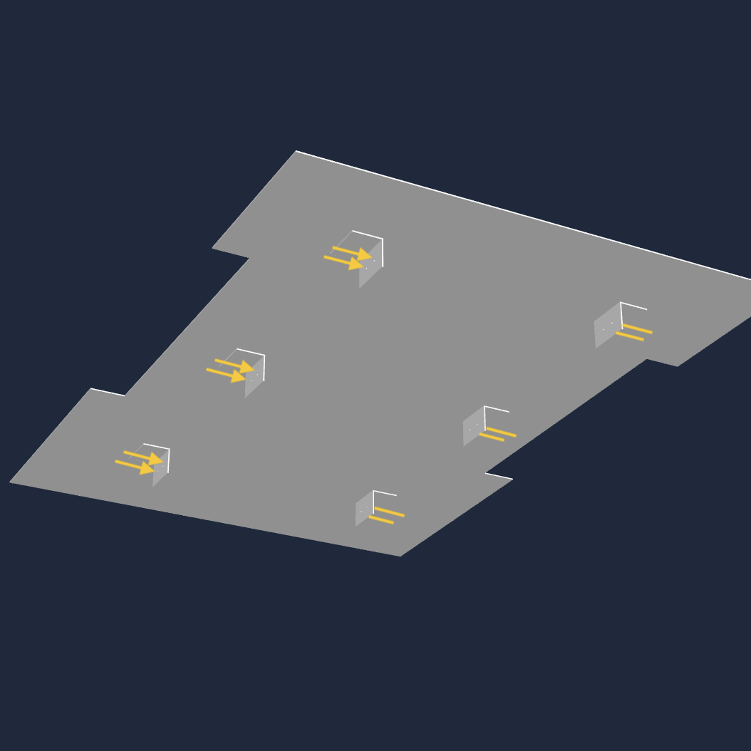
The 6061-T6 aluminum floor plate (detailed in Floor.pdf) ships pre-drilled with the full Ø 6.5 mm M6 clearance-hole matrix — no layout or drilling of the plate is required in the field. Before positioning, confirm the holes are clean and deburred and that the pattern matches the spec below.
The factory pattern uses a strict 1.5" edge offset so every screw lands dead-center on the 3"-wide sub-frame tubes:
- 6 structural anchoring brackets (mounting angles): 2 holes per bracket, hole centers 1.5" (38.1 mm) from the edge profile of the center floor section.
- Lateral outer frame edges (left and right flanges): 7 holes per side, each 1.5" (38.1 mm) inward from the outer physical edge of the aluminum plate.
2Final layering, structural bonding, and permanent torque
The sub-frame tubes arrive pre-drilled and pre-tapped with the matching M6 thread matrix — no field marking, drilling, or tapping is required; you fasten directly into the prepared frame.
Apply the 3"-wide self-adhesive EPDM isolation tape — 8694K122 — cleanly across the remaining bare steel sub-frame surface rows. This creates a complete non-conductive barrier — the only thing standing between the 6061-T6 aluminum and the structural carbon steel.
Using a manual cartridge gun, lay a thick, continuous triangular bead (≈ 8–10 mm tall) of Sika-Flex 252 down the center line of the EPDM tape layer.
Lower the aluminum floor plate onto the adhesive bed and compress uniformly until it seats flat.
Take M6 × 1.0 mm stainless button-head screws — 92095A487. Wet threads with Loctite 270/2701 (red) and thread each directly into the frame.
Drive fasteners with a 4 mm hex-bit socket on a calibrated torque wrench, working inside-out from the center brackets to the outer perimeter edges.
Cabin floor final torque: all M6 screws → 9.5 Nm (7 ft-lb).
Final assembly protocol
Wipe away any structural adhesive squeezed out at the margins using a plastic scraper and solvent cleaning cloth.
The assembly must sit completely undisturbed on the level shop floor for a minimum of 24 to 48 hours to allow the structural adhesive bed to fully cross-link before any vehicle movement or payload stress.
Torque reference
| Fastener | Location | Final torque |
|---|---|---|
| M16 × 1.5 Class 10.9 | Rear frame mounts (Chapter I, Step 3) | 200 Nm / 150 ft-lb |
| M16 × 1.5 Class 10.9 | Forward pivot hangers (Chapter I, Step 10) | 200 Nm / 150 ft-lb |
| M6 × 1.0 stainless | Aluminum floor to sub-frame (Chapter II, Step 2) | 9.5 Nm / 7 ft-lb |
⚠️ The 200 Nm figure is carried over from the original 5/8" Grade 8 spec. Confirm the correct torque for M16 × 1.5 mm Class 10.9 fasteners (and the matching wrench across-flats size) before final assembly.
Reference standards
- Ford Upfitter Guidelines — 2024 F-450 / F-550 / F-600
- AWS D1.1 — Structural Welding Code (Steel)
- SAE J429 — Mechanical and Material Requirements for Externally Threaded Fasteners